THE FOKKER AIRCRAFT PAGE.
ROLLS ROYCE TAY ENGINE.

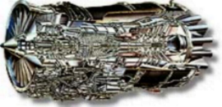
The tay engine is an axial flow , by-pass engine with two compressor spools. The Rolls royce tay is the combination of two highly successful engines. The high pressure system comes from the RB183-555 engine of the Fokker F28. The low pressure system comes from the RB211-53E4 "big fan" engine.
The combination of reliability , low fuel burn and remarkable low noise makes the Tay engine family very popular in aviation.
|
The Rolls-Royce Tay 620-15 is used on the first F-100 production aircraft , this because the 650-15 was not available . When it came available the F-100 was delivered with the 650 engine however it was also possible to get it with a 620 engine .The big advantage of the 650 was the better performance at higher altitudes and a better climb rate.The Fokker 70 is only delivered with Rolls Royce Tay 620-15 engines. |
Type of engine |
TAY 620-15 |
TAY 650-15 |
Thrust ( LB ) at SL/ISA |
13850 |
15100 |
Flat rated to ( c ) |
30 |
30 |
Inlet mass flow ( LB/sec ) |
408 |
425 |
Bypass ratio |
3.04 |
3.10 |
Overall pressure ratio |
16.0 |
16.4 |
Fan diameter (inch) |
44.0 |
44.8 |
Engine Weight (LB) |
3135 |
3340 |
Engine length (inch) |
94.8 |
94.8 |
Turbine entry temperature |
1305 K |
1386 K |
Cruise thrust ( FL300 . 0.73 MN ISA , in LB) |
2800 |
3200 |
SFC ( LB/LB/hr ) |
0.69 |
0,69 |
Fuel consumption (example 300 NM flight ) |
2063 KG |
2065 KG |
DESCRIPTION.
The engine consists of a number of modules.This gives the possibility to replace parts of the engine easily
The main components of the engine are:
LP compressor ( Fan )
The fan is single stage and has 22 " wide cord " blades. The IP compressor shaft drives the fan at the same speed. A nose cone with ice shedder gives the air to the fan at the optimum angle. The fan casing has acoustic lining to decrease the fan noise.The fan module is a line replaceable unit.
IP compressor
The axial flow Ip compressor has three stages. The Ip compressor connects to the three stage LP turbine. The LP shaft is inside the HP shaft. The IP compressor casing has an internal gearbox to operate at high speed and a low speed gear box . On the IP compressor casing are a front engine hoisting point , front and side mount . The IP compressor casing also carries the engine data plate.
HP compressor
The axial flow HP compressor has twelve stages. It connects to a two stage HP turbine , through a hollow drive shaft. Around the 7th stage is an annular bleed valve . On the rear end of the IP compressor casing are variable inlet guide vanes. They control the angle of the airflow into the HP compressor. On the HP compressor casing are two bleed air supply ducts , one on the 7 th stage and one on the 12 th stage. Air from those ducts goes to the aircraft bleed system.
Combustion section
The combustion section consists of 10 " tubo - annular " combustion liners . The tube type liners are in an annular casing. For flame spreading during start-up , the liners are interconnected together with tubes. In each liner is a fuel spray nozzle . Ignitor plugs are in liners No. 4 and No 8 only.
HP turbine
The HP turbine is a two stage axial flow turbine which connects to the HP compressor and high speed gear box.
LP turbine
The LP turbine is a three stage , axial flow turbine . It connects to the LP compressor and fan .
By-pass duct
The annular by-pass duct has three sections . The duct connects to the IP compressor casing and goes up to the mixer . The by-pass duct is of carbon fiber , with a honeycomb core , for noise reduction . On the duct are several panels for access to the HP system.
12 Lobe mixer
A twelve-lobe mixer gives a deep mixing of the by-pass flow and the core flow . The overall jet-pipe temperature and velocity decrease and as a result of this noise reduces.
Gearboxes
The engine-driven accessories are on two external gearboxes , the high speed gearbox and the low speed gearbox . The HP shaft turns the high speed gearbox . On the high speed gearbox are several components . The LP shaft turns the low speed gearbox . On the low speed gearbox are only the LP shaft governor and the N1 indicator generator.
During engine start , the starter motor turns the highspeed gearbox . The HP shaft turns the LP shaft by the airflow caused by the HP compressor.